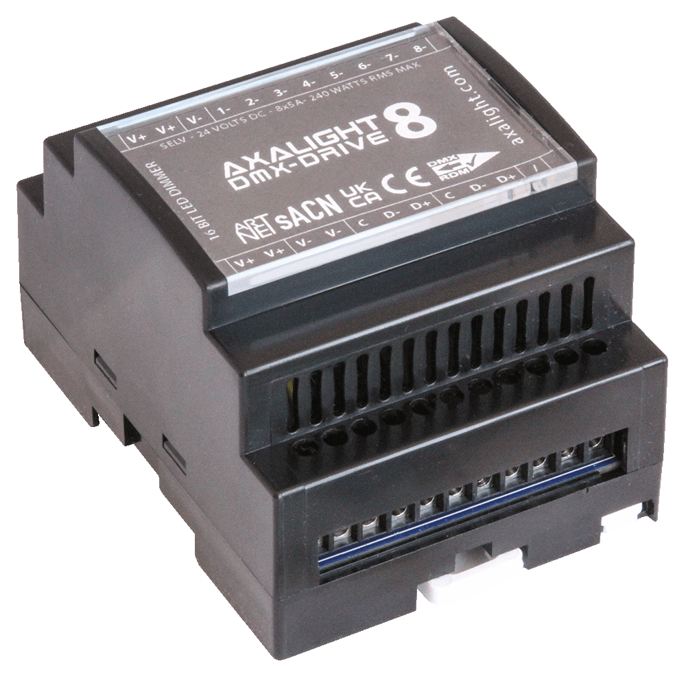
DMX-DRIVE 8 - DD8
DMX/RDM & WFI/ARTNET 16bit low voltage dimming and DIN rail flexibility for constant voltage LED applications.
(for wireless only applcations see our CLOUD DRIVE 8)
FEATURES
- DMX/RDM wired control input
- RDM remote configuration
- 8 x CV constant voltage LED control outputs
- 8-bit personality mode (8 channel footprint)
- 16-bit personality mode (16 channel footprint)
- Smoothed or non-smoothed personality modes
- Compact DIN rail format
- SELV DC supply input
- DMX IN/THRU connections
- Screw terminals (pluggable)
DMX-DRIVE 8
DMX 512 RDM
8 LED Output Ch.
16 & 8 Bit Dimming
24 Volts SELV
DIN Rail Mount
IP22 Dry Spaces
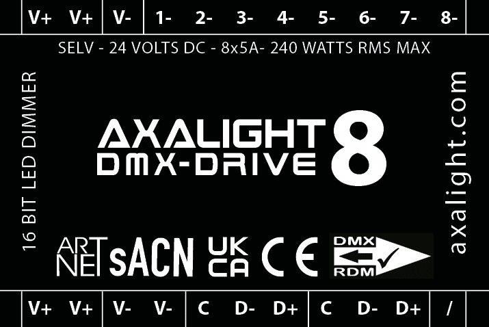
ELECTRICAL
- 24 Volt DC supply input
- Common anode (+)
- 8 x controlled cathode (-) outputs
- 5 Amps per channel load peak (120W)
- 10 Amps total RMS continuous load (240W)
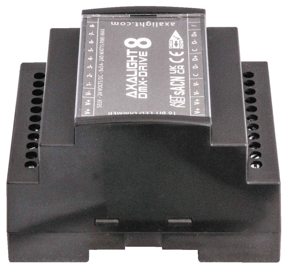
PHYSICAL
- 70W x 91H x 60D mm (110H with fixing tabs)
- 4 DIN rail modules wide
- 150 grams product weight
- IP22 protection rating
- PC/ABS/V0 rated enclosure
- -20° ~+50°C ambient temp
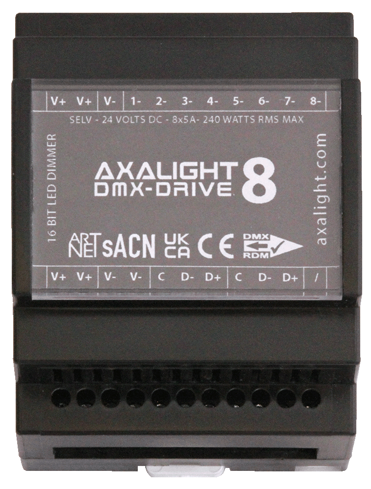
CONNECTIONS
- V+ | Supply Input / Link +24 Volts
- V- | Supply Input / Link 0 Volts (Common)
- 1- | Channel 1 output -
- 2- | Channel 2 output -
- 3- | Channel 3 output -
- 4- | Channel 4 output -
- 5- | Channel 5 output -
- 6- | Channel 6 output -
- 7- | Channel 7 output -
- 8- | Channel 8 output -
- Note | All V+ are linked internally
- Note | All V- are linked internally
- C | DMX common
- D- |DMX- data
- D+ | DMX- data
- Note | The two DMX ports are wired internally in parallel
POWER IN / THRU
The V+ and V- terminals are linked respectively within in the DD8. IN/THRU linking is allowable up-to absolute 10 Amps maximum per terminal.
INSTRUCTIONS
- For professional installation only
- Use SELV power supplies of 24 Volts DC
- Ensure power supplies are equiped with short circuit and over current protection
- Mount in vertical orientation with air vents slots top and bottom
- Ensure adequate airflow / ventiallation
- Make all connections before energising
- Terminal blocks can be unplugged by first removing DD8 front cover
- Test loads before connection to DD8
- Use RDM equiped controller/tester to configure DMX start address and personalaties
IMPORTANT
If removing front cover to access pluggable terminal strips, ensure correct orientation on refitting! The 8 large MOSFET devices are located at the TOP of the DD8.
